
Injection molding is the dominant manufacturing process for plastic parts at scale. It converts raw polymer pellets into finished components in seconds, producing everything from bottle caps to automotive dashboards with high precision and repeatability. Understanding how the process works helps engineers design better parts, avoid common defects, and communicate effectively with molders.
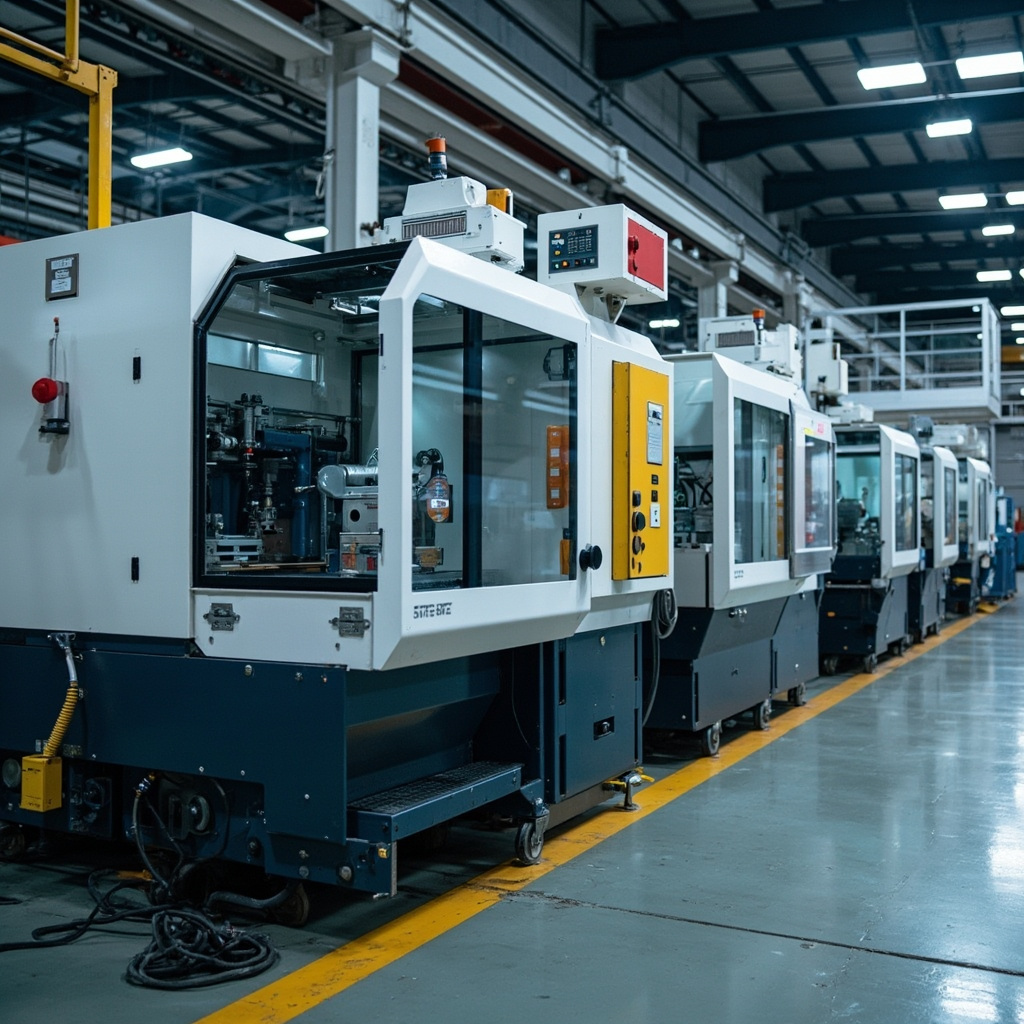
How Injection Molding Works: The Basic Cycle
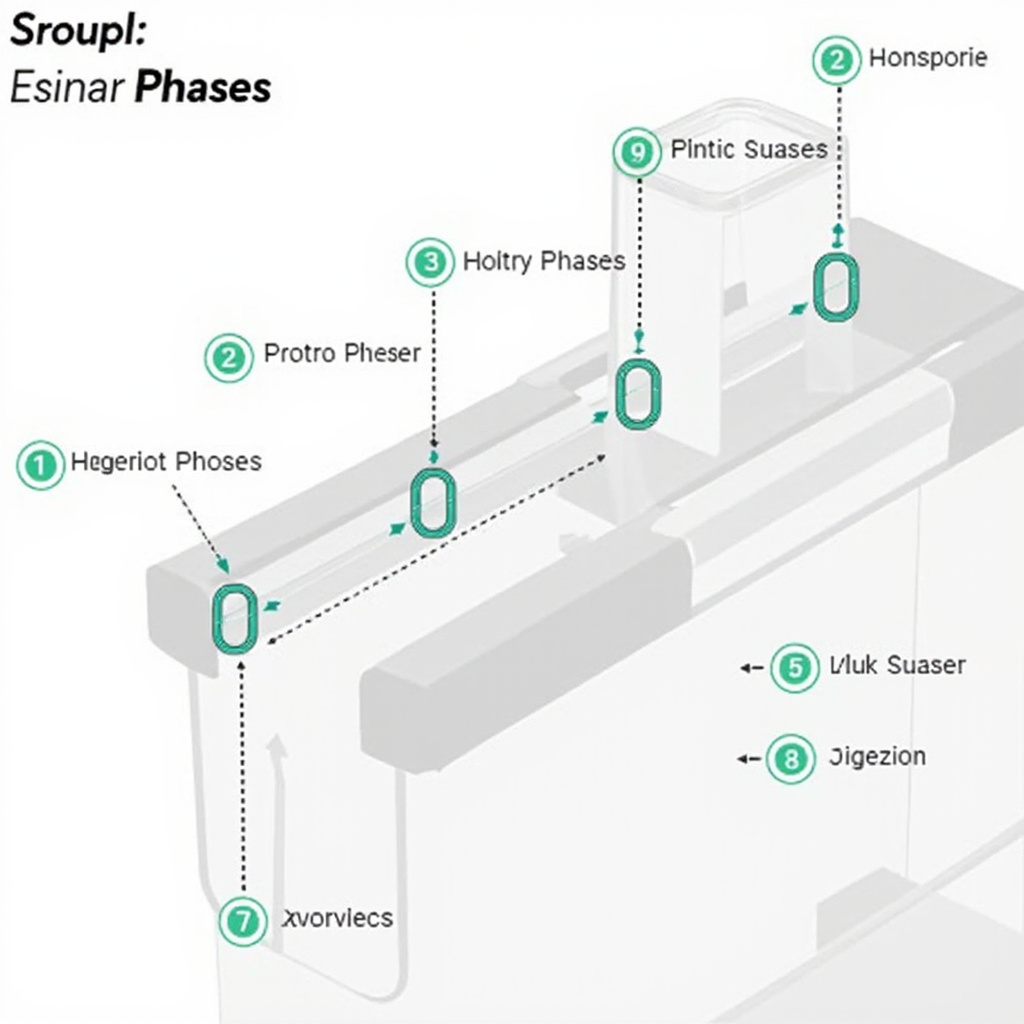
The injection molding cycle consists of five distinct phases, each with specific parameter controls that determine part quality.
1. Clamping
Before injection begins, the mold must be securely clamped shut. The clamping force must exceed the injection pressure (typically 60-150 MPa) to prevent flash—thin layers of material escaping the mold cavity at the parting line. Clamp tonnage is typically calculated at 3-8 tons per square inch of projected part area, depending on material and part geometry.
2. Injection
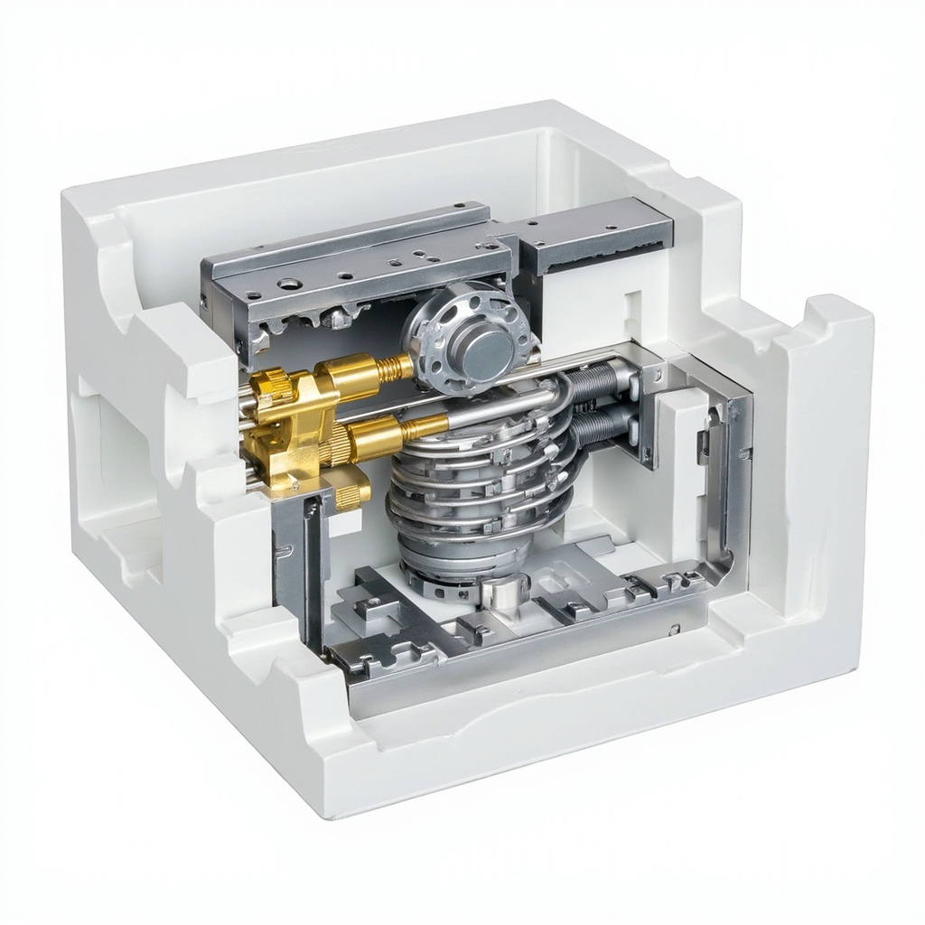
Plastic pellets are fed from a hopper into a heated barrel where a rotating screw melts and homogenizes the material. The molten plastic is then injected into the mold cavity at high speed and pressure. Injection speed and pressure profiles are critical—they must fill the cavity completely before the material begins to solidify.
3. Packing and Holding
After the cavity is filled, additional pressure (holding pressure) is applied to compensate for material shrinkage as the part cools. This phase typically lasts 5-20 seconds depending on wall thickness. Inadequate holding pressure results in sink marks and dimensional shortfalls.
4. Cooling
The part solidifies as heat transfers to the mold walls. Cooling time is the longest phase of the cycle, typically 10-60 seconds. Cooling channel design in the mold is critical—well-designed cooling reduces cycle time and improves part quality.
5. Ejection
Once the part has solidified sufficiently, the mold opens and an ejection system (typically spring-loaded pins or a stripper plate) pushes the part out of the cavity. Draft angles on part walls facilitate ejection. Ejection too early causes warpage; too late wastes cycle time.
주요 공정 매개변수
| 매개변수 | 일반적인 범위 | Effect on Part |
|---|---|---|
| 용융 온도 | 220-300 degrees C (material dependent) | Higher = better fill, more degradation risk |
| 금형 온도 | 20-120 degrees C | Higher = better surface, longer cycle |
| Injection Pressure | 60-150 MPa | Higher = better fill, flash risk |
| 압력 유지 | 40-80% of injection pressure | Compensates shrinkage, affects density |
| Cooling Time | 10-60 seconds | Longer = less warpage, slower cycle |
 id #ddd;”>Total Cycle Time |
15-120 seconds (typical) | Drives production cost per part |
Common Defects and Their Causes
싱크 자국
Dimensional voids or depressions on the surface, typically over thick sections or ribs. Caused by insufficient holding pressure, short holding time, or excessive melt temperature. Fix: increase packing pressure and time, reduce wall thickness transitions.
플래시
Thin excess material at the parting line or around cores. Caused by insufficient clamp force, excessive injection pressure, or worn mold. Fix: increase clamp tonnage, reduce injection pressure, inspect mold for wear.
뒤틀림
Non-planar distortion of the finished part. Caused by uneven cooling, excessive shear from high injection speed, or residual stress from insufficient annealing. Fix: balance cooling channels, adjust gate location, use模具temperature control.
Short Shot
Incomplete filling—the cavity is only partially filled. Caused by insufficient injection pressure/speed, material that is too cold, or clogged gates. Fix: increase injection parameters, verify material drying, check gate clearance.
용접선
Visible lines where two flow fronts meet in the cavity. Caused by multiple gate locations, complex geometry, or low
melt temperature. Weld lines are weak points and stress concentrators. Fix: raise melt temperature, redesign gate locations, add venting at weld line locations.
Burning Marks
Dark spots or streaks near the end of fill, typically from trapped air that ignites. Caused by excessive injection speed, poor venting, or excessive moisture in material. Fix: reduce injection speed, add vacuum vents, verify material dryness.
Injection Molding vs. Other Processes
| 팩터 | 사출 성형 | CNC 가공 | 3D 프린팅 |
|---|---|---|---|
| Best for Quantity | 1,000개 이상의 부품 | 1-500 parts | 1-100 parts |
| 관용 | +/-0.05 mm typical | +/-0.01 mm achievable | +/-0.1-0.5 mm typical |
| 표면 마감 | Mold finish dependent | Tool mark dependent | Layer lines visible |
| 툴링 비용 | High ($10K-$500K+) | Low-medium | 없음 |
| 자재 낭비 | Sprue/runner system | Chip evacuation | Support structures |
Our Injection Molding Capabilities
We offer injection molding services for prototyping and low-to-mid-volume production:
- Multi-cavity tooling for competitive unit pricing at moderate volumes
- Overmolding and insert molding for multi-material assemblies
- Hot runner and cold runner systems optimized for part requirements
- Full DFM analysis before mold construction to minimize defects
자주 묻는 질문
When does Injection Molding Process: A Complete Step-by-Step Guide make sense?
Injection Molding Process: A Complete Step-by-Step Guide makes sense when the part volume, material choice, geometry, and repeatability needs justify mold design and tooling investment.
What design factors matter most for Injection Molding Process: A Complete Step-by-Step Guide?
벽 두께, 리브, 보스, 이형각, 게이트 위치, 수축, 분할선, 이젝션 등은 모두 성형 부품의 품질에 영향을 미칩니다.
금형 제작 전에 어떤 정보가 필요한가요?
공급업체는 3D 모델, 재질, 예상 연간 생산량, 외관 요구 사항, 공차 요구 사항 및 조립 또는 기능 테스트 관련 요구 사항을 확인해야 합니다.
What is the biggest risk in Injection Molding Process: A Complete Step-by-Step Guide?
가장 큰 위험은 실제 적용 환경에서 재료의 거동, 수축, 유동 및 부품의 기능을 충분히 검증하지 않은 상태에서 금형을 승인하는 것입니다.
For drawing-specific DFM, material, tooling and production support after using this guide, review our plastic injection molding services and send the drawing, resin requirements and expected volume.

