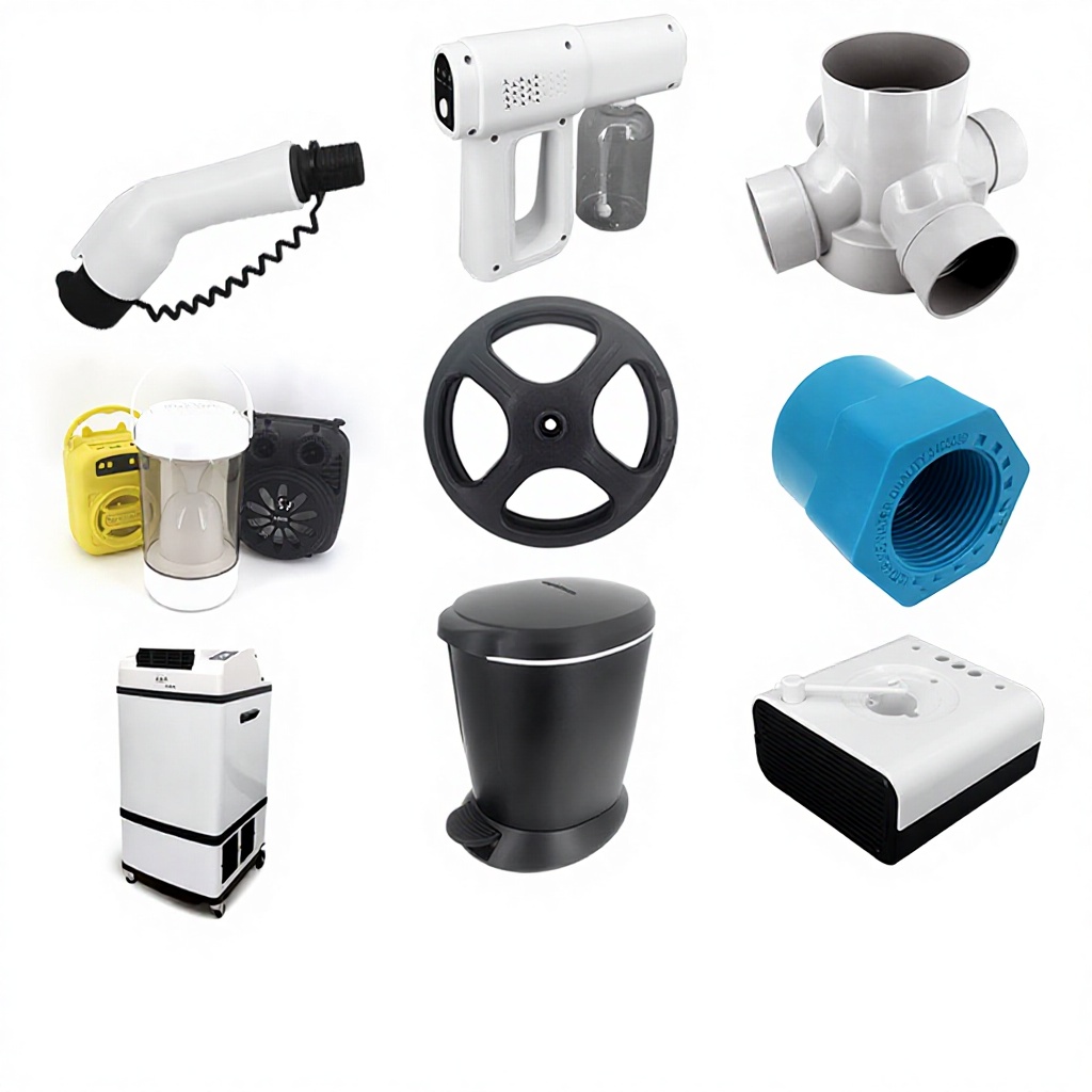
The cavity generally forms the exterior of a molded part, and the core forms features such as bores, recesses and internal walls. Review the parting line, gate, cooling and ejection together. Cosmetic faces and functional dimensions should drive where these features are placed.
엔지니어링 및 조달 팀을 위해
Reviewing Core and Cavity Design Before Tooling?
Core and cavity decisions control parting lines, draft, cooling, ejection and many sources of flash or warpage. Review these items against the real resin and inspection plan before mold steel is cut.
- Confirm parting line and side-action requirements from the CAD model
- Review cooling, gate and ejection together rather than as separate checks
- Define cosmetic zones, tolerances and annual volume before tooling release
Understanding Core and Cavity Fundamentals
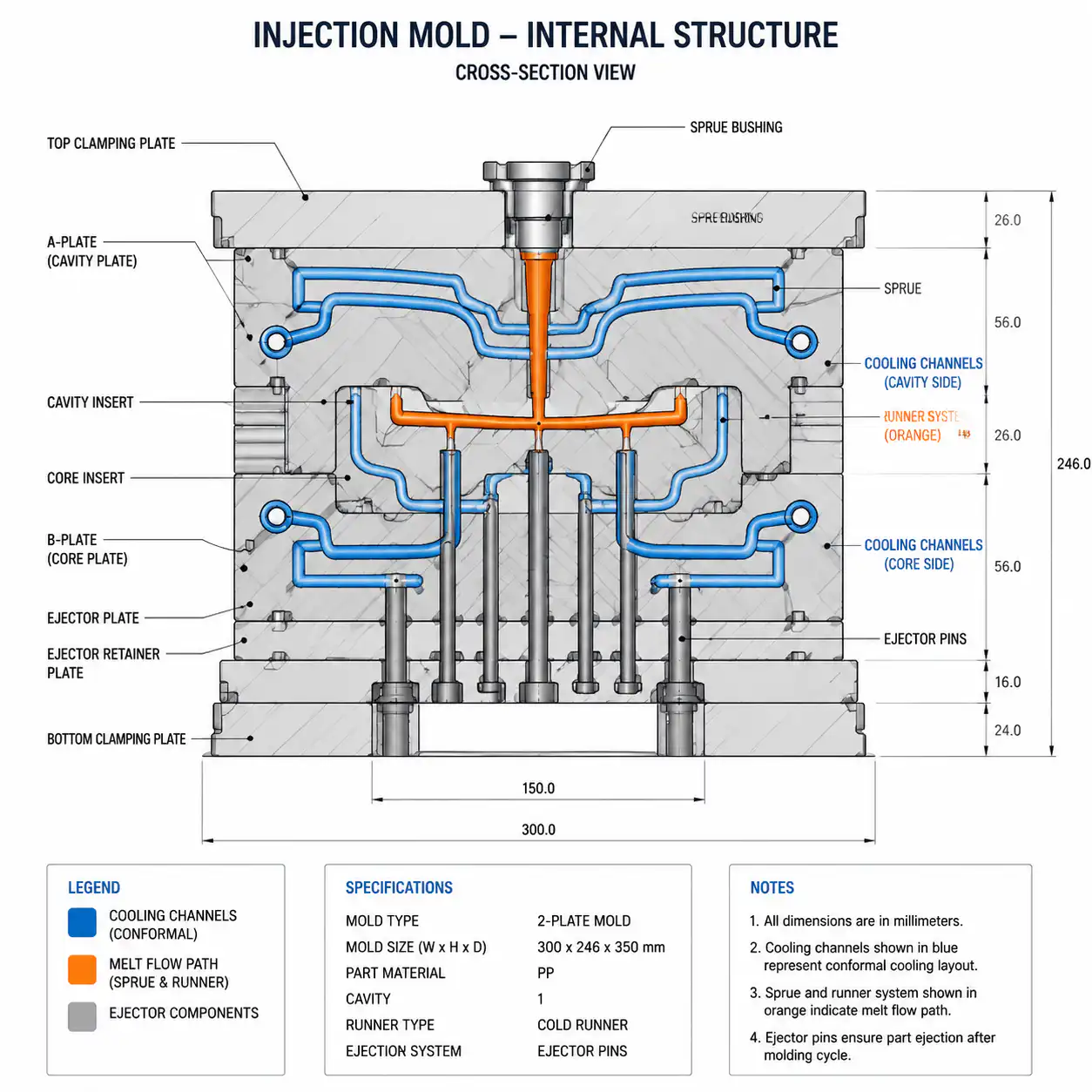
The cavity often forms the outside profile and the core forms the inside profile. In a conventional two-plate tool, the core is often on the moving side, but the part geometry, retention and ejection plan determine the arrangement. See the Protolabs guide to core and cavity placement.

At DFM review, agree on visible witness lines, locations where flash could affect assembly, and how the part will remain on the intended side before ejection.
Parting Line Strategy: Where Form Meets Function
The parting line is where your core and cavity halves separate, and its placement is the single most consequential decision in mold design. A flat, planar parting line along a single plane is the simplest and least expensive option — but real-world parts rarely offer that luxury. Stepped parting lines follow part geometry when features prevent a flat split, adding roughly 10-15% to tooling cost while resolving undercut situations without side actions. When parts have holes or features perpendicular to the mold opening direction, side actions (also called slides or lifters) extend the parting line into three dimensions, increasing both tooling complexity by 20-40% and cycle time by 2-5 seconds per side action.
Strategic parting line placement minimizes visible witness lines on cosmetic surfaces. For consumer-facing products, position the parting line along natural edges or transitions rather than across large flat faces. When working with glass-filled materials, keep the parting line at least 0.5mm away from sharp corners to prevent chipping during ejection. For multi-cavity tools, ensure the parting line plane is consistent across all cavities to maintain uniform clamp force distribution. A parting line mismatch of just 0.03mm creates visible flash that costs real money in secondary deflashing operations — typically $0.05-$0.15 per part for manual trimming, or $0.02-$0.05 for automated tumbling.
Draft Review for Cores and Cavities
Choose draft for the release direction, resin, depth, texture and ejection method. Internal features can grip the core as the part shrinks, so inspect deep sections separately.
Review textured faces with the toolmaker and texture supplier. Mark areas where draft or witness lines could alter fit, appearance or a sealing face.
| 주요 기능 | Draft review | 확인해야 할 사항 |
|---|---|---|
| Deep core | Review depth, texture and resin grip. | Check scuffing, distortion and ejection force on samples. |
| Rib or boss | Check each side relative to the release direction. | Confirm local wall thickness and functional fit. |
| Cosmetic wall | Coordinate the surface finish and pull direction. | Compare witness lines and marks to the appearance sample. |
| Shutoff or undercut | Review release, steel contact and any side action. | Confirm flash acceptance and maintenance access. |
Cooling Layout and Dimensional Stability
Cooling layout affects dimensional consistency and cycle time. Ask the toolmaker to identify isolated core tips, thick sections and regions with limited water access. Use trial parts to verify distortion and dimensional repeatability.
Deep or narrow cores can have limited space for channels. Review conventional channels, baffles or conformal cooling against tool strength, maintenance access and the actual heat load.
Ejector Placement: Freeing the Part Without Damage
Ejector pin placement determines whether your part pops out cleanly or emerges with stress marks, deformation, and the telltale circular witness lines of poorly planned ejection. The fundamental rule: eject where the part is strongest, not where it’s most convenient for the mold base layout. Eject against ribs and bosses from behind, never against thin unsupported walls that will deflect. Ejector pins should contact the part through the B-side (core side), and the total ejector area must be sufficient to overcome the part’s adhesion to the core — which for deep-draw parts with minimal draft can exceed 50 MPa of holding force.
Use the cosmetic and functional requirements to decide where pin marks are acceptable. Review blades, sleeves or a stripper plate where the geometry needs a different distribution of ejection force.
- Check wall transitions, ribs and bosses where thick areas could affect sink or warpage.
- Mark critical dimensions, cosmetic faces, undercuts and the intended release direction.
- Review gates, cooling and ejector positions on the same tool concept before sign-off.

산업별 적용 분야 매트릭스
| 신청 | Core and cavity review focus |
|---|---|
| Automotive bracket | Identify assembly datums, witness lines and loaded bosses. |
| Electronics enclosure | Check connector opening, seal face, exterior finish and ejector marks. |
| Medical equipment housing | Review cleanable geometry, acceptance criteria and any required documentation. |
| Industrial housing | Review ribs, threaded inserts, replaceable details and inspection access. |
Cost Decision Framework: Core-Cavity Design Economics
Compare tooling quotes using the same cavity count, tool material, surface finish, side actions, sample rounds and inspection scope. Ask each supplier to separate tooling, qualification and recurring production costs.
- Compare one-cavity and multicavity options against the launch and repeat-order quantities.
- Ask which side actions, inserts and maintenance items are included in the quote.
- Agree how sample approval and dimensional reports will be handled before production.
For a volume comparison, spread the one-time tooling cost over the expected accepted quantity and add the quoted part, secondary-operation and inspection costs. State how scrap, tool maintenance and design changes are treated.
Common Core-Cavity Defects and Solutions
| 결함 | What to inspect before changing the tool |
|---|---|
| Parting-line flash | Check shutoff contact and tool alignment, then review the process window and clamp settings. |
| Scuffing or drag | Check draft, texture and part retention on the core. |
| 뒤틀림 | Review wall thickness, gate orientation, cooling balance and conditioning after molding. |
| Ejector marks | Check support, pin position, local wall thickness and ejection timing. |
프로젝트에 나일론 플라스틱을 선택해야 하는 이유
정밀 제조
한 지붕 아래 30개 이상의 CNC 및 사출 성형 라인
ISO 9001:2015 인증 획득
인증된 품질 관리 시스템, 전체 검사 보고서
15~25일의 리드 타임
신속한 처리 및 긴급 처리 옵션 제공
전 세계 배송
북미, 유럽, 아시아행 항공 및 해상 화물 운송
Download Our Core & Cavity Design Guide
재료 선정 표, 설계 지침 및 공급업체 평가 체크리스트를 다루는 무료 PDF 참고 가이드.
관련 기사
Complete guide to A/B/C/D finish grades for injection molds
Edge treatment selection for manufacturability and strength
ISO 2768 and DIN standards for plastic part tolerances
Process selection guide for prototyping and production

자주 묻는 질문
What’s the difference between the core and cavity in injection molding?
The cavity generally forms the exterior, and the core generally forms recesses, bores and internal surfaces. Assign fixed and moving sides based on the gate, part retention and ejection arrangement.
What is the minimum draft angle for deep cores?
There is no single minimum for every deep core. The toolmaker should review depth, resin shrinkage, texture, release direction and ejector access together.
How do I prevent flash at the parting line?
Inspect the location and repeatability of the flash. Verify shutoff condition, tool alignment, clamp and process settings before making changes. Agree what is acceptable at sealing and mating surfaces.
Can I water-cool deep cores effectively?
Deep-core cooling depends on space for channels, required core strength and operating conditions. Review the channel layout with the toolmaker and measure whether sample temperatures and dimensions stabilize during a trial.
기술적 출처 및 검증
공급업체 데이터를 검증 자료로 활용하되, 실제 사용 조건에서 정확한 등급 및 부품을 직접 시험하는 것을 대체하는 용도로 사용해서는 안 됩니다.
Buyer Checklist Before Core and Cavity Review
| Review Point | Buyer Should Confirm | 그것이 중요한 이유 |
|---|---|---|
| Parting line | Can it hide flash risk and support clean ejection? | Parting line choice affects tool life and cosmetic quality |
| Cooling layout | Are hot spots and cycle time targets defined? | Poor cooling leads to warp, sink and unstable output |
| Gate strategy | Is fill balance more important than gate visibility? | Gate location changes weld lines and shrink behavior |
| Ejection | Will the part release without mark-sensitive damage? | Too much ejection force causes scuffing and distortion |
For a mold design review, attach the CAD model and controlled drawing. Mark cosmetic faces, critical fits, insert locations and annual volume. Note the requested sample and inspection records.