Plastic machining tolerances are controlled by the material, stock condition, geometry, toolpath, workholding, temperature, inspection method and quantity. A tolerance copied from a metal drawing may be technically possible on one feature but unreliable across a flexible housing, thin wall or large plate. The correct approach is to set functional tolerances first, then use datums, process controls and inspection evidence to protect the assembly.
This guide covers CNC-machined POM, nylon, PEEK, PEI, PTFE, UHMW-PE, acrylic, PC and other engineering plastics. It is intended for buyers and engineers preparing a drawing or RFQ, not as a promise that one tolerance applies to every material or part size.
Typical tolerance direction by plastic family
| Material family | Common dimensional risk | Design response |
|---|---|---|
| POM / Delrin | Generally stable, but thin walls and heat from cutting can move | Use balanced roughing and finish passes; control burrs on bores and gears |
| Nylon / PA | Moisture absorption and stress release change dimensions | Specify the conditioning state and inspect after equalization |
| PEEK / PEI | Residual stress, heat generation and stock condition affect fit | Use conservative stock removal, support thin features and validate free-state dimensions |
| PTFE / UHMW-PE | Low stiffness, creep and thermal expansion make thin features difficult | Use larger wall sections, controlled clamping and realistic clearance |
| PC / acrylic | Heat, stress cracking, scratches and optical surface damage | Use sharp tools, coolant strategy suited to the grade and a protected finish plan |
Material-specific tolerances should be coordinated with the CNC plastic machining service guide. For PEEK and Delrin production routes, use the dedicated PEEK CNC 그리고 Delrin CNC 페이지.
Use datums and functional dimensions
A controlled datum scheme is more valuable than a long list of tight bilateral tolerances. Identify the surface that locates the part, the feature that sets orientation and the features that control assembly. Apply position, flatness, perpendicularity, profile and runout only where the function requires them. A bore used for a bearing, a sealing face and a mounting hole pattern may need different controls even when they are close together.
| 주요 기능 | Useful drawing control | Inspection question |
|---|---|---|
| Mounting hole pattern | True position to functional datums | Will the mating part assemble without forcing the pattern? |
| Bearing or shaft bore | Size, roundness, position and surface finish | Is the clearance or interference valid at service temperature? |
| Sealing face | Flatness, profile and surface finish | Can the seal maintain compression across the full face? |
| Thin cover wall | Profile or thickness with a free-state condition | Will the feature distort under clamping or measurement force? |
| Gear or wear surface | Tooth/profile, concentricity and runout | Will the material creep or wear change the intended motion? |
Machining strategy for stable plastic dimensions
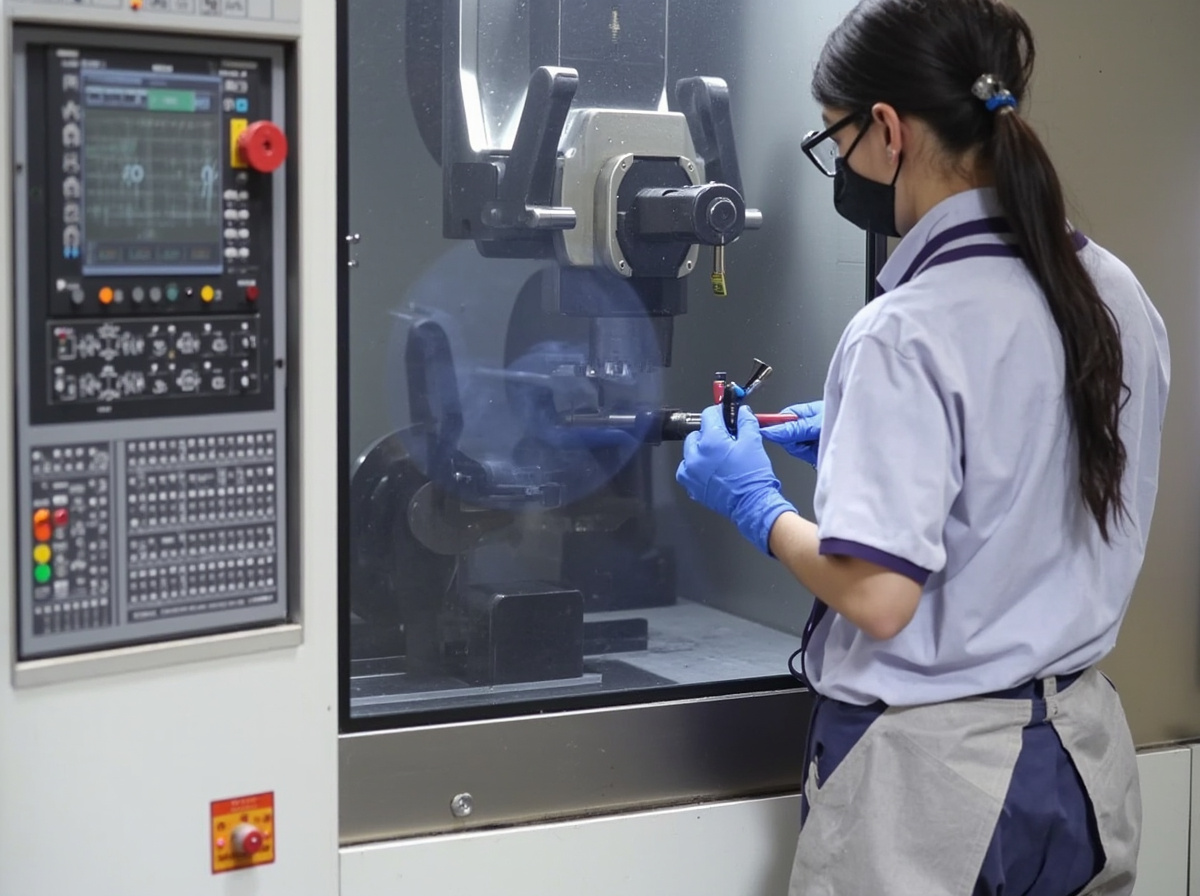
Plastic parts generally benefit from staged material removal. Rough-machine the stock while leaving a controlled allowance, allow the part to relax when the material and geometry require it, then finish-machine critical datums and mating features. Avoid clamping thin walls directly against a hard jaw if the inspection condition is free state. Soft jaws, vacuum fixtures, support nests and sacrificial tabs can reduce deformation.
- Use sharp, suitable tools and remove heat through cutting strategy rather than excessive pressure.
- Keep the part supported close to thin walls, deep pockets and long unsupported spans.
- Balance stock removal to reduce stress release and bowing.
- Separate roughing and finishing tools when edge condition or surface finish is critical.
- Control coolant, air, cleaning chemicals and drying so the material is not altered before inspection.
- Deburr without rounding a functional edge or changing a sealing feature.
Temperature, moisture and warpage
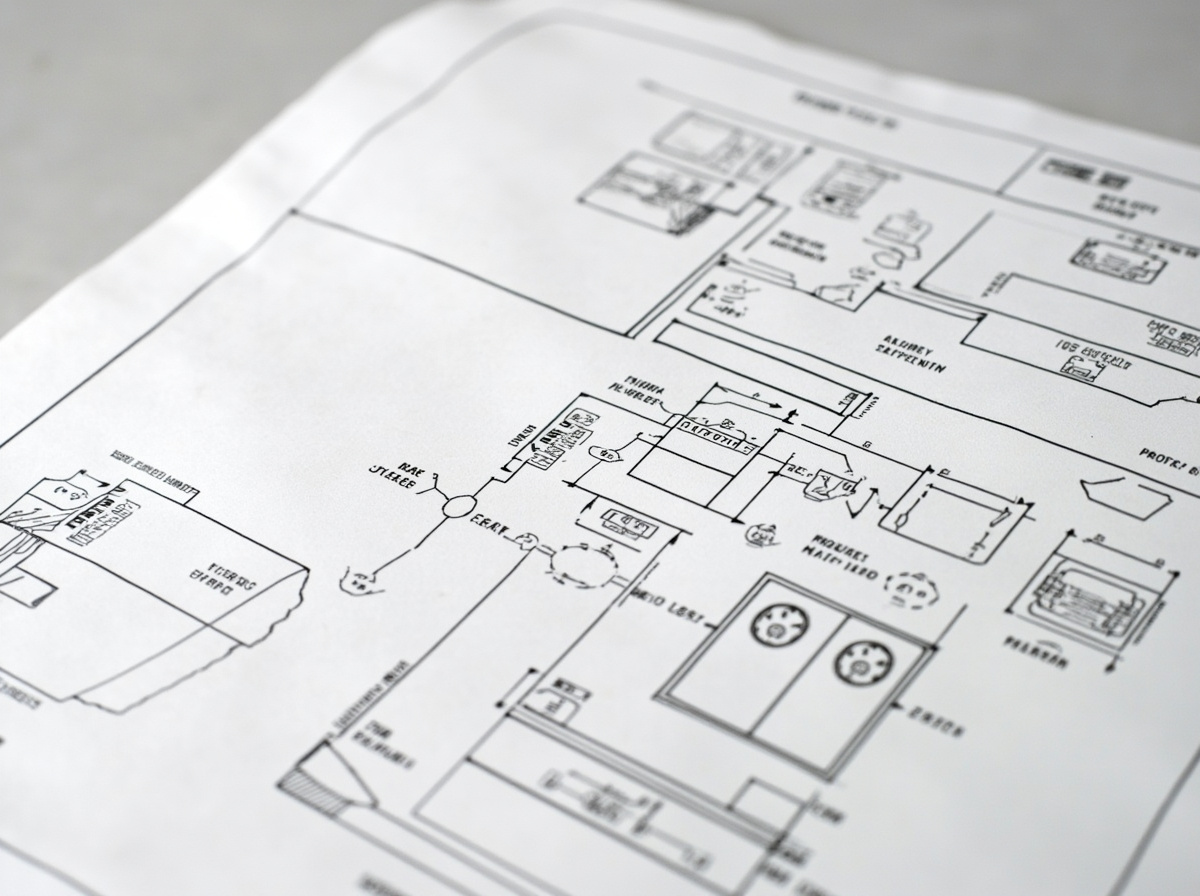
Large plastic parts can change dimension during the day as the shop temperature changes. Nylon can move after moisture conditioning; PEEK, PEI and PTFE can release stock stress; UHMW-PE can creep under fixture or assembly load. The drawing should state the temperature and material condition for inspection when the tolerance is close to the expected movement.
Do not correct a flexible part by over-tightening the fixture during measurement. Record whether the part is supported, clamped, assembled or free. When a flatness or profile requirement is functional, inspect the part in the same support condition used in the product. For a tight assembly, inspect the mating components together and confirm clearance at the service temperature.
Inspection checklist for CNC plastic parts
- Confirm drawing revision, material grade, filler, color and stock certification.
- Verify datums and the fixture reproduce the functional assembly condition.
- Control temperature, humidity and conditioning time before measurement.
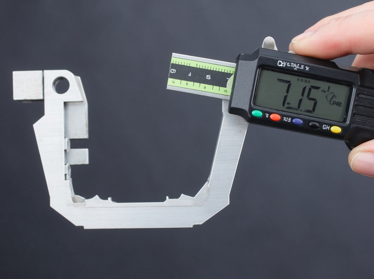
- Use CMM, vision, height gauge, bore gauge or calibrated hand tools appropriate to the feature.
- Record measurement uncertainty when the tolerance is close to the instrument capability.
- Inspect critical bores, hole position, flatness, wall thickness, profile, threads and surface finish.
- Separate cosmetic marks, machining burrs and functional nonconformities in the report.
RFQ information that improves tolerance decisions
Send the 3D CAD model, controlled drawing, material grade, quantity, annual demand, surface finish, critical features, mating parts, assembly load, service temperature, humidity or chemicals and required inspection report. Mark the features that must assemble, seal, rotate or carry load. State whether dimensions are measured free state, in a fixture or assembled. We can then recommend a machining sequence, stock condition and inspection plan instead of treating every dimension as equally critical.
When secondary operations improve the result
Some plastic features are more stable when they are machined after a near-net process or after the part has relaxed. Reaming a bearing bore, facing a seal land, drilling a final hole pattern or tapping an insert seat can improve local function, but the allowance, workholding and inspection datums must be planned from the beginning. A secondary operation is not a license to ignore material movement; it is a way to concentrate precision where the assembly needs it.
For larger plates and housings, ask whether the stock should be rough-cut, conditioned and then finish-machined. PEEK, PEI, nylon and acetal can all respond to heat or stress release in different ways. A supplier should state how the part will be supported during finishing and whether the final inspection will be free state, lightly supported or assembled. This detail often explains why two quotations offer different tolerance limits for the same model.
Inspection reports should distinguish size error, form error, position error and deformation. A hole can be the correct diameter but in the wrong location; a flat face can meet size but fail flatness; a flexible wall can pass when clamped and fail when released. Reporting the type of error helps the design team choose a correction instead of simply requesting a tighter general tolerance.
For repeat orders, retain the approved first-article report, tool list, fixture revision and material lot information. This gives the supplier and buyer a reference when dimensions drift after a tool change, stock change or new operator setup.
When a tolerance is unusually tight, ask for the supplier’s expected process capability and measurement uncertainty before the order is placed. It is better to agree a realistic feature control and verification plan during design review than to discover after machining that the instrument, fixture or material condition cannot support the drawing.
For parts that will be assembled repeatedly, add a functional fit check to the dimensional report. A gauge or mating component can reveal burrs, edge damage, friction or clamp force that a coordinate measurement alone does not capture.
Include the fit result for the first article and retain the approved gauge or mating reference for repeat production.
This is especially important for flexible plastics, sliding interfaces and sealing features.
Buyer Pain Points Behind Plastic Tolerance Disputes
- Every dimension is assigned the same tight limit regardless of assembly function.
- Stock condition, moisture, temperature, stress relief, and free-state inspection are not stated.
- Workholding datums differ from drawing and inspection datums.
- Thin walls are deformed by clamping or contact measurement.
How Nylon Plastic Supports the Project
Nylon Plastic has supported material selection and finished plastic-part manufacturing since 2005. The same project review can connect plastic-specific workholding, machining sequence, conditioning, datum planning, and inspection, so buyers do not have to evaluate each production decision in isolation.
- Review the drawing, material, quantity, critical features, and use environment before quotation.
- Compare 3D printing, CNC machining, rapid tooling, and production molding when more than one route is practical.
- Define samples, dimensional reports, material documents, traceability, and acceptance criteria before release.
관련 읽기
자주 묻는 질문
What tolerance can CNC machining hold in plastic?
Capability depends on material, stock, geometry, wall thickness, feature location, workholding, temperature, moisture, and inspection. Define only function-critical limits tightly.
Are plastic machining tolerances the same as metal tolerances?
No. Plastics are generally less stiff and more responsive to heat, stress, moisture, and clamping, so datum and inspection conditions need extra care.
How should nylon be conditioned before inspection?
Define whether the part is inspected dry, conditioned to a specified environment, or after service exposure, then allow it to stabilize before final measurement.
What belongs in a tolerance RFQ?
Include CAD, drawing, material and stock condition, quantity, datums, mating parts, critical dimensions, service environment, finish, conditioning, and report format.
Request a CNC Plastic Tolerance Review
Send the drawing, material, mating conditions, and inspection requirements to establish functional and achievable limits.