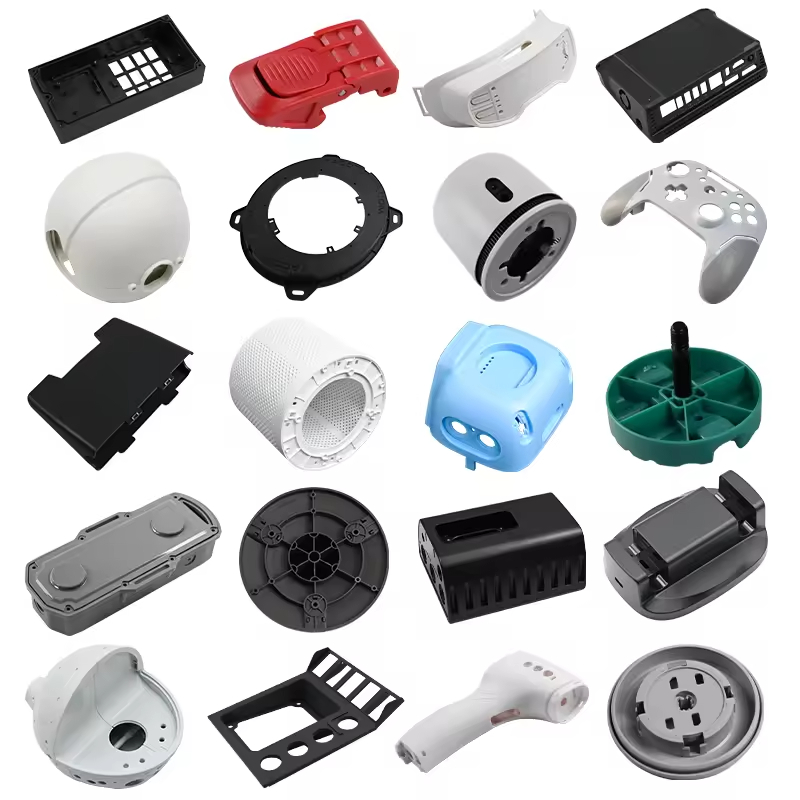
사출 금형 설계 소개
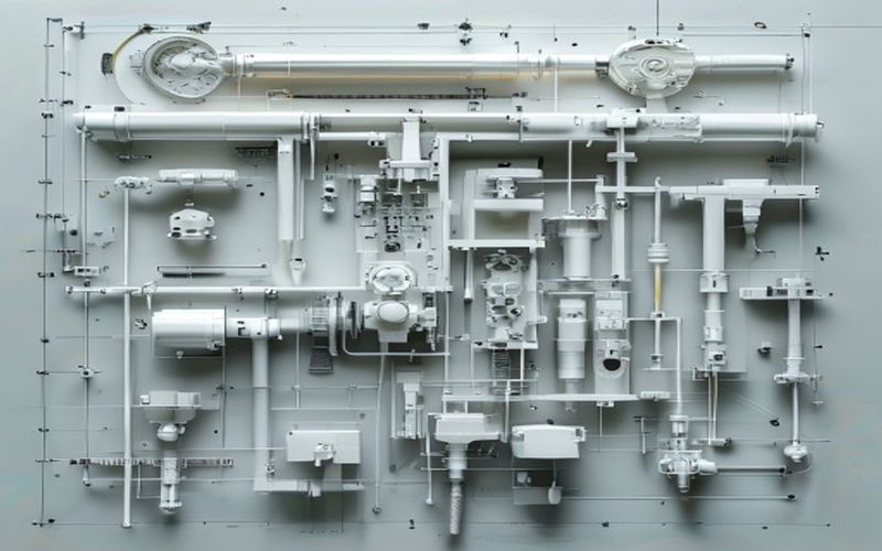
사출 금형 설계는 성공적인 플라스틱 부품 제조의 기초입니다. 잘 설계된 금형은 일관된 부품 품질, 효율적인 생산 주기 및 긴 금형 수명을 보장합니다. 이 가이드는 모든 엔지니어가 이해해야 할 필수 원칙을 다룹니다.
1. 균일한 벽 두께
사출 성형에서는 벽 두께를 일정하게 유지하는 것이 매우 중요합니다. 변화가 생기면 차열이 발생하여 뒤틀림, 싱크 마크 및 내부 응력이 발생합니다.
재료별 권장 벽 두께
| 재료 | 권장 두께(mm) |
|---|---|
| ABS | 1.2 - 3.5 |
| PP | 0.8 - 3.8 |
| PC | 1.0 - 3.8 |
| 나일론(PA6/PA66) | 0.8 - 3.0 |
| POM | 1.0 - 3.0 |
2. 부품 릴리스를 위한 드래프트 각도
구배 각도를 통해 성형된 부품이 금형 캐비티에서 깨끗하게 방출될 수 있습니다. 구배가 적절하지 않으면 부품이 달라붙어 결함 및 금형 손상이 발생할 수 있습니다.
- 최소 초안: 매끄러운 표면을 위한 0.5° - 1°
- 텍스처 표면: 텍스처 깊이에 따라 2° - 5°
- 심층 기능: 통풍을 증가시켜 재료 수축을 보정합니다.
3. 적절한 리브 디자인
4. 게이트 위치 전략
게이트 배치는 채우기 패턴, 용접 라인 및 파트 모양에 영향을 줍니다. 고려하십시오:
- 흐름 길이: 압력 강하를 줄이기 위해 최소화
- 용접 라인 배치: 중요하지 않은 영역에 위치
- 모양: 가능하면 보이지 않는 영역에 게이트 숨기기
- 부품 기능: 하중을 견디는 기능 근처의 게이트 피하기
5. 냉각 시스템 설계
효율적인 냉각으로 사이클 시간을 단축하고 부품 품질을 개선합니다. 주요 고려 사항
- 균일한 냉각 채널 간격(채널 직경의 2~3배)
- 딥 코어를 위한 배플 및 버블러
- 복잡한 형상을 위한 컨포멀 냉각
- 적절한 물 유량(난류 체제)
피해야 할 일반적인 디자인 실수
- 적절한 메커니즘(리프터, 슬라이드)이 없는 언더컷
- 날카로운 내부 모서리로 인한 스트레스 집중
- 불충분한 환기로 인해 화상 및 짧은 촬영이 발생합니다.
- 치수 계산에서 재료 수축 무시하기
결론
이러한 사출 금형 설계 원칙을 따르면 일관된 품질로 부품을 제조할 수 있습니다. 제품 설계자와 금형 엔지니어 간의 초기 협업을 통해 나중에 많은 비용이 드는 수정 작업을 방지할 수 있습니다.
관련 리소스
관련 리소스
관련 리소스
자주 묻는 질문
When does Injection Mold Design Principles — Building Quality Molds from the Ground Up make sense?
Injection Mold Design Principles — Building Quality Molds from the Ground Up makes sense when the part volume, material choice, geometry, and repeatability needs justify mold design and tooling investment.
What design factors matter most for Injection Mold Design Principles — Building Quality Molds from the Ground Up?
벽 두께, 리브, 보스, 이형각, 게이트 위치, 수축, 분할선, 이젝션 등은 모두 성형 부품의 품질에 영향을 미칩니다.
금형 제작 전에 어떤 정보가 필요한가요?
공급업체는 3D 모델, 재질, 예상 연간 생산량, 외관 요구 사항, 공차 요구 사항 및 조립 또는 기능 테스트 관련 요구 사항을 확인해야 합니다.
What is the biggest risk in Injection Mold Design Principles — Building Quality Molds from the Ground Up?
가장 큰 위험은 실제 적용 환경에서 재료의 거동, 수축, 유동 및 부품의 기능을 충분히 검증하지 않은 상태에서 금형을 승인하는 것입니다.
How to Review an Injection Mold Design Before Steel
A good mold design review connects the molded part to the actual production machine, resin, cycle, inspection method and expected tool life. A drawing can look complete while still leaving important decisions open: where the gate will be placed, how air will leave the cavity, how the part will be released, how cooling will reach thick sections and how worn components will be replaced. Before steel is cut, ask for a review that explains these decisions in relation to your part requirements.
Start with the controlled part drawing and mark critical-to-function dimensions, sealing surfaces, assembly datums, cosmetic zones, inserts and areas that cannot show ejector marks or gate vestige. Add the resin grade, filler content, color, annual volume, target cycle and molding machine limits. These inputs determine whether a simple single-cavity tool, a multi-cavity tool, a family mold or a more automated solution is appropriate.
| Design area | Buyer risk | Evidence to request |
|---|---|---|
| Parting line and shutoffs | Flash, mismatch, sealing damage or an unacceptable cosmetic line | Parting-line mark-up, shutoff angles and sample standard |
| Gate and runner | Weld lines, air traps, poor packing, fiber orientation or visible vestige | Gate location, fill direction and runner-balance concept |
| Cooling layout | Long cycle, uneven shrinkage, sink, warpage or local overheating | Cooling circuit drawing and temperature-control assumptions |
| Ejection | Sticking, deformation, drag marks or pin witness on a critical surface | Ejector map, draft review and release-force plan |
| Maintenance access | Long downtime when wear parts or slides need service | Replaceable insert list, spare parts and service access |
Gate, Venting and Cooling Decisions
Gate location should follow the part’s functional and cosmetic priorities. A gate near a thick section may improve packing but can increase sink or vestige. A gate on a cosmetic face may shorten flow length but create an appearance problem. For glass-filled resin, the flow direction can influence stiffness, shrinkage and anisotropy. Multi-cavity tools also need a balanced runner system so each cavity receives a consistent melt history.
Venting is part of the filling design, not a late repair. End-of-fill areas, deep ribs, blind pockets, slides and weld-line regions need a practical escape path for air and gas. Inadequate venting can show up as burn marks, short fill, gloss differences or unstable filling. Ask how vents will be machined, cleaned and protected during maintenance.
Cooling should cover thick bosses, ribs, inserts and areas near the gate while keeping sufficient steel around the cavity. The circuit should be reachable for cleaning and leak checks. Baffles, bubblers or conformal channels may be considered when conventional drilling cannot control temperature. The best choice depends on cycle target, part geometry, steel layout and the value of reducing dimensional variation.
Tool Architecture and Steel Selection
Tool architecture should match volume and resin severity. Prototype and low-volume programs often benefit from accessible inserts and a design that can be changed after the first trial. Higher-volume programs usually need robust cavity details, balanced cooling, reliable automation interfaces and serviceable wear components. For abrasive or corrosive materials, cavity steel, hardness, surface treatment and replaceable gates deserve a documented decision.
| Project condition | Design emphasis | Questions for the quotation |
|---|---|---|
| Prototype or pilot | Fast changes and accessible inserts | Which features can be adjusted after T1? |
| Repeat production | Cycle stability, balance and maintenance access | What shots, cycle and service interval are supported? |
| Abrasive engineering resin | Wear resistance at gates, slides and shutoffs | Which steel and spare inserts are included? |
| Tight cosmetic requirement | Gate, polish, texture, vent and parting-line control | What sample is used for appearance approval? |
Trial, Inspection and Tool Acceptance
A mold should be accepted against an agreed trial plan, not only because the machine produces a part. Record resin grade and lot, machine, mold temperature, melt temperature, injection profile, holding conditions, cycle and cavity identification. Review short shots, flash, sink, burn marks, weld lines, ejection, warpage and dimensions. For multi-cavity tools, inspect cavity-to-cavity variation instead of relying on one representative part.
Before production release, request the approved mold drawing, steel and component list, cooling and pneumatic diagrams, cavity identification, spare-parts list, maintenance instructions and dimensional report. Critical features should be measured with the agreed datum and conditioning state. If a dimension is affected by moisture or temperature, define when the measurement is taken. We can support DFM review, mold design, fabrication, sampling and corrective changes as one connected project.
For an RFQ, send CAD, controlled drawing, resin data, volume, target cycle, machine information, cosmetic zones, critical dimensions, inserts, post-molding assembly and required tests. A complete input package allows a mold supplier to price the actual risk rather than adding broad assumptions to the quotation.