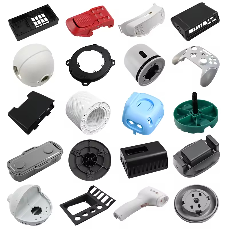
1. Introduction: Why Ribs and Bosses Matter in Injection Molding
In injection molding, part designers constantly face a fundamental challenge: achieving structural stiffness and strength while keeping wall thickness uniform. Simply thickening walls adds material cost, extends cycle time, and introduces warping, sink marks, and internal voids. Ribs and bosses provide the solution.
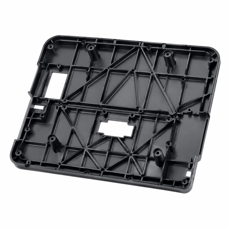
Ribs add material away from the bending axis to increase section stiffness. The benefit depends on rib shape, direction, span and support. Check the loaded part rather than assigning a fixed stiffness multiplier.
Bosses are cylindrical projections designed to accept self-tapping screws, threaded inserts, or locating pins. They concentrate mounting forces and must be designed carefully to avoid sink marks on the opposing cosmetic surface.
This guide covers the proven design rules, dimension tables, and common pitfalls for ribs and bosses in injection molded plastic components. Whether you are designing consumer electronics enclosures, automotive interior parts, or medical device housings, these principles are starting guidelines that must be checked against the selected material, mold and application.
2. Rib Design Rules and Best Practices
2.1 Rib Thickness
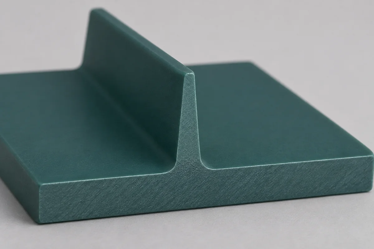
For initial layout, Protolabs’ molding guide uses a rib-to-adjacent-wall ratio of 40–60%. Measure the rib at the root and check the combined local mass where it joins the wall. The range is a starting point. Resin, surface finish, gate, cooling and the required cosmetic limit determine whether the detail is acceptable.
| Example nominal wall | Initial rib root range | Next check |
|---|---|---|
| 1.5 mm | 0.60–0.90 mm | Confirm tip fill after adding draft |
| 2.0 mm | 0.80–1.20 mm | Check sink on the opposite face and the fillet at the junction |
| 3.0 mm | 1.20–1.80 mm | Review intersections, cooling and appearance on a molded sample |
2.2 Rib Height
Set height for the load case. Check the remaining tip thickness after draft, steel access, venting and ejection. Compare a shorter or divided rib when a tall thin feature is difficult to fill or release.
2.3 Draft Angle
Set draft on each surface in the pull direction with the moldmaker. The grade, depth, surface texture and tooling route affect the required angle. Confirm texture and mold release before finalizing the drawing.
2.4 Rib Spacing
Leave enough room between ribs for cavity machining, cooling and ejection. Check local mass at the wall and any intersections, particularly behind the visible face.
3. Boss Design Rules
3.1 Boss Outer Diameter
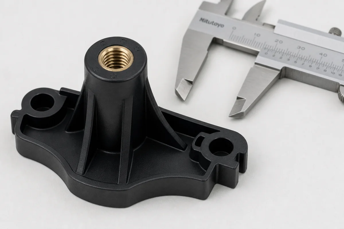
Start with the exact fastener maker’s pilot hole, engagement and boss recommendations for the resin. Review the boss outer wall and the opposite cosmetic face together. Protolabs’ boss design guidance shows why the tooling route can change wall and draft decisions.
3.2 Boss Height and Aspect Ratio
Set height from engagement, stack-up and core pin support. Check fill at the tip and stability during installation. For a tall boss, evaluate a cored, gusseted geometry with the molder.
3.3 Draft Angle for Bosses
Review internal and external draft with the toolmaker. Dimension the critical pilot hole at a defined depth because draft changes the diameter along the core.
4. Common Design Mistakes and Solutions
4.1 Thick Ribs Causing Sink Marks
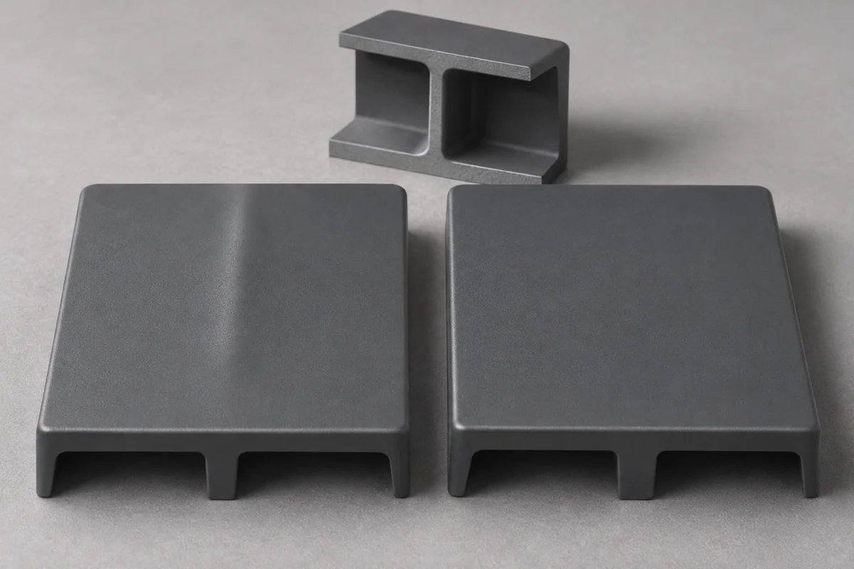
Local thickness at a rib junction can pull the opposite face inward as it cools. Reduce accumulated mass, consider gate and pack changes, then inspect an actual molded surface under agreed lighting.
4.2 Tall Bosses Causing Short Shots
Check tip thickness, gate path, venting and the supported material process window. Verify filling and core-pin stability in a molding trial.
4.3 Insufficient Draft Causing Ejection Issues
Review the direction of pull, texture and ejection layout. Look for drag marks or stress whitening on the first samples and adjust tooling as needed.
4.4 Missing Corner Radius at Rib-Base Intersection
Use a fillet that eases the transition without creating a thick junction. Verify stress and sink together where a rib meets a loaded or visible wall.
5. Gusset and Corner Reinforcement Design
5.1 Gusset Plates for Boss Reinforcement
Gussets are triangular support plates that connect a boss to the part base wall. They dramatically increase lateral stiffness and bending resistance at minimal material cost. Design rules for gussets:
- Gusset thickness: Same as or slightly less than rib thickness (≤60% of nominal wall)
- Gusset height: 50–75% of boss height
- Gusset width at base: 1.5–2.0 × boss outer diameter
- Number of gussets: Typically 3–4 equally spaced around the boss circumference
- Draft: Same draft angle as the boss or rib
5.2 Corner Reinforcement
Use a rib or gusset where the load path needs support. Compare corner deflection with representative loads, and check tool access, radii and the cosmetic surface opposite the junction.
5.3 Cross-Rib and Honeycomb Patterns
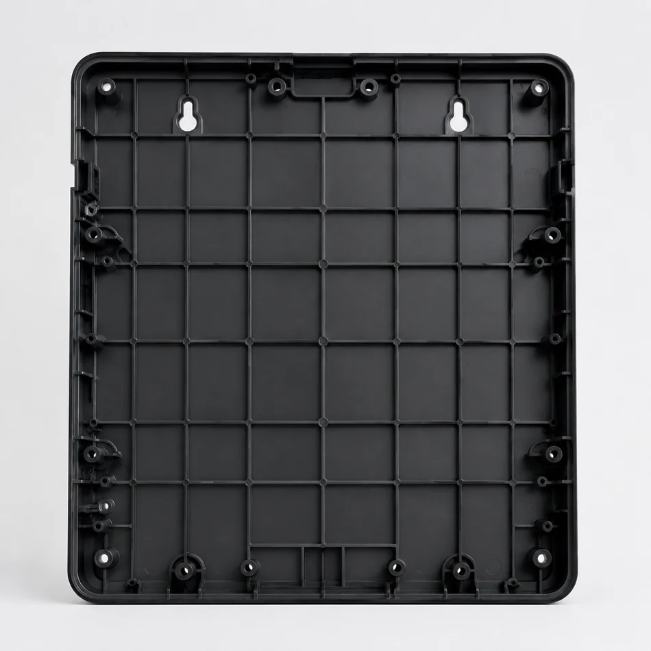
Check intersections in a grid for accumulated thickness, trapped air and local warp. Use sample testing to compare stiffness and surface appearance with a simpler rib layout.
6. Screw Boss Dimensions to Confirm Before Tooling
| Drawing item | Information to agree | First-sample check |
|---|---|---|
| Fastener and pilot hole | Exact fastener part number, resin grade and pilot diameter at a defined depth | Assembly and stripping torque, boss cracking |
| Boss diameter and engagement | Boss wall, useful thread engagement, pull-out load and assembly cycles | Pull-out, fit and repeated assembly where required |
| Ribs and gussets | Nominal wall, root and tip thickness, draft and fillets | Filling, ejection marks and visible sink |
| Cosmetic face and assembly | Appearance sample, critical datums and surface tolerance | Compare molded surfaces under agreed lighting and check mating fit |
7. Frequently Asked Questions
What is the minimum practical rib thickness?
Confirm the rib tip after draft against the material, flow path and tool. Review filling and ejection on a representative molding before releasing the drawing.
When should I add a rib instead of thickening the wall?
Try ribs when bending stiffness or support is needed without adding a thick section. Check stiffness in the actual load direction and inspect for sink and warp.
How do I size a boss for a screw?
Start with the fastener supplier’s guidance for the exact screw and resin. Confirm the pilot diameter at a stated depth, engagement and boss wall, then test torque and pull-out on molded parts.
How can I reduce sink marks near ribs?
Limit local thickness and check where ribs, bosses and fillets intersect. Review gates, packing and cooling with the molder, then compare samples to the appearance criteria.
Confirm Rib and Boss Details in the DFM Review
Use the dimension tables as starting geometry, then check the selected resin, nominal wall, cosmetic surface, gate direction, mold construction and ejection conditions. Bosses also need the actual screw or insert specification and assembly load; one ratio does not establish a finished-part guarantee.
For a molded component, review the plastic injection molding service and DFM scope. Share the drawing revision, mating components, screw/insert type, required torque or pull-out test, quantity, and any unacceptable sink or warpage. Request a Rib and Boss DFM Review.
Reference guidance: Protolabs boss-design considerations 그리고 Xometry rib-design guidance. Final dimensions remain dependent on the actual material and mold.
관련 읽기
- 사출 성형 벽 두께 설계 가이드
- Threaded Inserts for Plastic Parts: Design and Installation
- Plastic Part Tolerances and Molding Standards
Request a Rib and Boss DFM Review
Upload the drawing below for a manufacturability review, or see our 나일론 사출 성형 서비스.