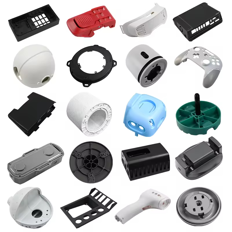
Plastic part tolerance stack-up is the combined effect of every dimension, clearance, datum relationship, material movement, and assembly condition that controls fit. An injection-molded housing can meet each isolated drawing dimension and still bind, rattle, misalign, leak, or show an unacceptable cover gap when the assembly chain is not analyzed as a system.
The practical goal is not to make every dimension tighter. It is to identify the functional path, place variation where the assembly can absorb it, and verify the result with molded parts measured under the same conditions used for acceptance.
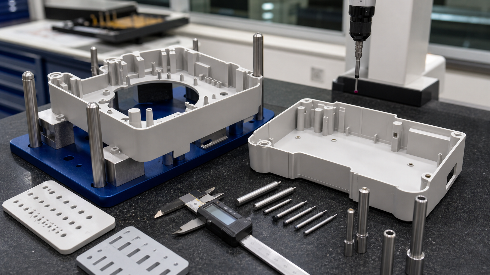
Start with the Functional Tolerance Chain
Write the assembly question before assigning tolerances. A cover chain may run from locating boss to fastener, housing wall, and seal; a sliding chain may run from guide datum through bore, shaft, and end stop. Include mating parts, fasteners, gasket compression, adhesive, and fixture constraints when relevant.
A worst-case review adds maximum contributors in one direction. A statistical review may use measured distributions only when the process is stable and the quality plan states the method; it must not hide an uncontrolled mold, material, or assembly condition.
Datum Strategy and GD&T
Primary datum A should represent the surface or axis that seats the part in service. Datum B controls the first locating direction, and datum C constrains the remaining degree of freedom without forcing a warped part flat. A parting-line datum may be convenient for inspection but wrong for assembly.
Use position, profile, flatness, perpendicularity, or runout where the function requires them. Define free-state or fixture measurement, and specify whether a screwed cover is inspected under installed clamp condition.
Clearance Allocation for Plastic Assemblies
Clearance must absorb the combined movement of both mating parts, not only the nominal gap visible on the CAD model. Consider dimensional tolerance, shrinkage, moisture, temperature, warpage, tool wear, burrs, coating or texture, and the assembly direction. A sliding fit needs running clearance; a locating fit may need controlled interference; a snap fit needs enough lead-in and recovery space to avoid cracking or permanent set.
| Assembly requirement | Main variation to review | Buyer acceptance question |
|---|---|---|
| Sliding or telescoping fit | Opposing size limits, warpage, temperature, surface texture | Does the minimum clearance remain functional after conditioning? |
| Locating boss and hole | True position, hole shrinkage, boss ovality, fixture datum | Will the parts locate without forcing one component out of position? |
| Seal or gasket interface | Flatness, compression range, molding distortion, clamp load | Is the minimum compression maintained without overloading the seal? |
| Cosmetic cover gap | Profile, parting line, screw pull-down, thermal movement | Is the visible gap evaluated on assembled production-intent parts? |
| Snap-fit or clip | Beam thickness, deflection, shrinkage, fiber direction, assembly force | Does the clip assemble repeatedly without cracking or losing retention? |
Shrinkage, Warpage, and Resin Effects
Injection-molded dimensions are influenced by resin grade, moisture, filler, flow direction, wall thickness, packing, cooling, gate location, and ejection. Semi-crystalline resins can show greater directional and post-mold movement than many amorphous grades. Glass-filled grades can improve stiffness while increasing anisotropy.
다음의 injection molding tolerance guide for individual molded-part dimensions; review the mating components and functional chain together when defining assembly acceptance.
For gate location and fiber-flow effects, see the gate design guide before steel release.
Feature, Risk, and Control Matrix
| Feature or risk | Why stack-up grows | Design, tool, or process response |
|---|---|---|
| Large molded housing | Cooling gradient, wall transition, and free-state distortion | Use functional datums, balanced cooling, appropriate ribs, and an assembled inspection fixture |
| Boss-hole pattern | Position variation accumulates across spacing and cavity direction | Define true position to functional datums and validate the complete pattern, not one hole |
| Long sliding rail | Thermal movement, bow, twist, and opposing part variation | Allocate running clearance, check the full travel path, and test at service temperature |
| Glass-filled resin | Fiber orientation creates directional shrinkage and stiffness differences | Align gate and flow review with the critical direction; confirm resin grade and conditioning |
| Multi-cavity tool | Cavity-to-cavity offsets can shift mating features | Identify cavity in reports, compare cavity means, and set a cavity-specific correction plan |
Inspection Checklist Before Approval
| Inspection item | What to define before sampling |
|---|---|
| Drawing and datums | Revision, ballooned characteristics, functional A/B/C datums, GD&T, and free-state or fixture condition |
| 자재 상태 | Resin grade, filler, lot, drying or conditioning record, and time from molding to measurement |
| Measurement method | CMM, optical scan, gauge, pins, profile fixture, resolution, calibration, and temperature |
| Sampling plan | First-off quantity, cavity identification, machine, process condition, and repeat samples after stabilization |
| Assembly validation | Mate real components, record insertion force or gap, test the functional range, and retain accepted samples |
우리의 사출 성형 서비스 can review the part, mold, resin, and inspection plan together.
다음의 플라스틱 부품 검사 및 계측 가이드 when defining the measurement method and report for sample approval.
자주 묻는 질문
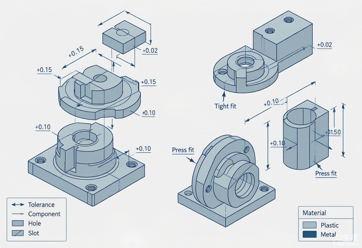
What is tolerance stack-up in a plastic part assembly?
It is the combined effect of multiple dimensions, position errors, clearances, material movement, and assembly conditions that determine whether mating parts fit and function.
What datum should be used for an injection-molded assembly?
Use the surface, axis, or feature that actually locates the part in service. The mold parting line is not automatically the correct datum. Define whether measurement is free-state or performed in an assembly-simulating fixture.
How do shrinkage and warpage affect the stack-up?
Shrinkage changes nominal dimensions and warpage changes relationships between features. Flow direction, wall thickness, cooling, packing, resin grade, filler, moisture, and temperature should be included in the risk review.
How much clearance should a molded plastic assembly have?
There is no universal value. Clearance depends on material pair, feature size, fit type, temperature, moisture, surface condition, process capability, and the amount of warpage or positional variation verified by samples.
What should be inspected before approving the mold?
Inspect ballooned drawing characteristics, functional datums, critical positions, cavity variation, material condition, flatness or profile, and the assembled function using a defined method, sample plan, and acceptance record.
Request a Plastic Assembly Fit Review
Use tolerance stack-up review when a molded housing, cover, guide, clip or seal meets isolated dimensions but still has an assembly-fit risk. Nylon Plastic can review the functional chain with the part, material, mold and inspection plan.
견적서 작성 전에 포함해야 할 사항 및 합의 사항
For an RFQ, send the CAD assembly, controlled drawings, resin and grade, annual volume, critical features, fit or sealing requirement, target capability, inspection temperature, and required report format. We can then separate a mold correction from a drawing issue, material movement from fixture error, and a true assembly risk from a non-functional tight tolerance.
- Include the mating-part drawings, assembly sequence and revision, datum scheme, target gap or clearance, seal compression or insertion-force requirement, and the allowed design changes.
- Identify the stage: design review, new mold, sample correction or repeat production. Include quantity, tooling and cavity identification, available measured samples and destination/timing.
- Separate predicted worst-case limits from statistical estimates based on stable process data. Agree the measurement fixture, restraint, temperature, moisture state and sample approval record for the actual assembly.
The review can identify which contributor, datum, mold correction or inspection condition needs attention before quotation or approval. Final fit requires representative mating components and an agreed assembly test; tightening every drawing dimension is not a substitute.