
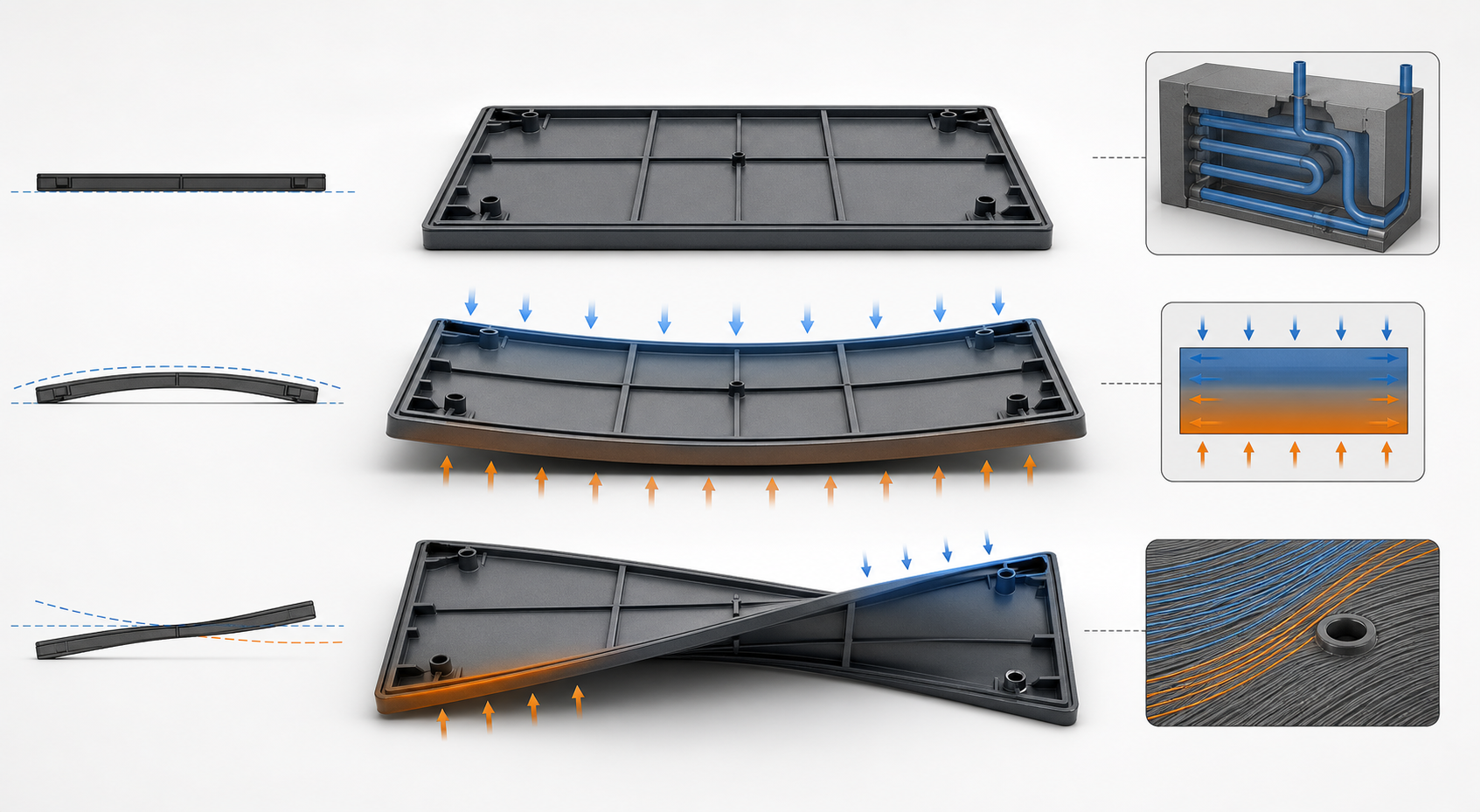
Warpage in injection molding is out-of-plane distortion caused by unequal shrinkage, cooling, flow orientation, packing or part restraint. It can appear as bow, twist, corner lift, panel oil-canning, or a hole pattern that shifts after the part is released from the fixture. A part may meet several local dimensions and still fail assembly because the complete surface has moved.
For a buyer, the first question is not which machine setting should be changed. The first question is whether the symptom is true molded warpage, ordinary shrinkage, sink, fixture deformation, moisture movement or measurement error. Correct identification protects the tool, prevents repeated trial shots, and gives the supplier enough evidence to propose a controlled fix.
What warpage looks like and why it matters
Warpage is easiest to recognize when the part is inspected in a defined free-state condition. A flat cover may show a raised edge or a concave center. A long housing may twist so that one mounting foot no longer contacts the assembly plane. A ribbed panel may bow toward the heavy rib side because thick and thin regions cool and shrink at different rates. Glass or carbon fiber grades can add directional movement because the fibers orient with flow.
Record the location, direction and repeatability of the distortion. If the same corner rises on every shot, the cause may be a consistent cooling, gate or geometry imbalance. If the direction changes after conditioning, the resin may be moisture-sensitive or the inspection state may be uncontrolled. If a part becomes flat only when clamped, the fixture may be hiding the problem rather than solving it.
Separate warpage from similar defects
| Observed symptom | What it may indicate | Useful confirmation |
|---|---|---|
| Panel bows after release | Differential cooling, packing or wall thickness | Free-state flatness/profile scan and cooling record |
| One corner lifts | Local hot spot, gate imbalance or rib concentration | Map the corner by cavity and compare mold cooling circuits |
| Hole pattern shifts with the panel | Global distortion rather than a single hole-size error | Measure hole position to stable datums and scan the full panel |
| Surface depression near a rib | Sink mark or local packing shortage | Inspect the opposite cosmetic surface and section a sample if needed |
| Part changes after clamping | Fixture distortion or flexible-wall compliance | Repeat measurement free, lightly supported and assembled |
| Movement after drying or conditioning | Moisture or post-molding relaxation | Record mass, humidity, temperature and conditioning time |
Use the broader injection molding defects guide for a general defect map. The mold flow and DFM guide is useful when gate, cooling or wall-thickness changes are under review, while the injection molding service page explains the production route. This page is limited to diagnosing and correcting warpage so a project team can assign the right evidence and owner.
Warpage cause, evidence and corrective action
| Cause group | Evidence to collect | Likely correction direction |
|---|---|---|
| 재료 | Resin grade, filler, lot, moisture condition and shrinkage direction | Confirm grade, dry correctly, review filled-resin orientation and shrinkage data |
| Machine/process | Melt temperature, mold temperature, fill profile, transfer point, packing and cooling time | Establish a stable window and compare short shots and packed parts |
| Mold | Gate location, cavity balance, cooling circuit temperature and vent condition | Balance flow and cooling, improve vents, or modify the gate/cooling layout |
| 기하학 | Wall map, rib-to-wall ratio, bosses, corners and thickness transitions | Balance walls, core heavy sections, add appropriate radii and reduce abrupt transitions |
| Inspection | Datum scheme, support condition, temperature, humidity and fixture force | Define free-state inspection and use a repeatable fixture only for functional checks |
Do not change several variables at once. A supplier should first identify whether the distortion follows material flow, cavity number, cooling circuit, mold temperature or a particular feature. A short-shot sequence can show the advancing flow front and weld locations. A cavity comparison can reveal whether one cavity has a different gate restriction or cooling response. A process-window record lets the buyer distinguish a stable correction from a single favorable sample.
Diagnostic sequence for a production part
- Confirm the symptom. Photograph the part on a flat reference, record the free-state condition, and mark the highest and lowest points.
- Confirm the material. Check exact grade, reinforcement, color, lot, drying record and any regrind percentage.
- Separate machine and cavity effects. Record machine, cavity, shot number, cycle time and process settings for each sample.
- Map the geometry. Compare flatness, profile, hole position, wall thickness and rib locations against the drawing datums.
- Check the tool. Review gate vestige, vents, cooling circuit temperatures, insert fit, ejector support and parting-line condition.
- Repeat after conditioning. For nylon and other moisture-sensitive materials, document temperature, humidity and conditioning time before deciding whether the issue is permanent.
For flatness and profile, a CMM or structured-light scan can reveal the shape of the error. Hand measurements are useful for screening but can miss a smooth bow or distort a flexible wall. The inspection report should show the support condition, datum alignment, temperature and whether the part was measured before or after assembly.
Process corrections that should be tested
Process changes should be made inside a documented window. Packing that is too low can leave uneven shrinkage, while packing that is too high can force material into a constrained region and increase stress. Fill speed can alter orientation and the timing of pressure transfer. Melt and mold temperature affect viscosity, frozen-layer growth and cooling balance. Longer cooling can reduce movement in some geometries, but it does not replace a badly balanced tool.
- Use a repeatable fill profile and record the transfer position.
- Compare packing pressure and time using part weight and dimensional response.
- Control mold temperature by circuit and cavity, not only by machine display.
- Verify that cooling time is long enough for safe ejection without making cycle assumptions the only evidence.
- Use a stable drying and conditioning procedure for moisture-sensitive grades.
- Record cavity-specific dimensions instead of averaging all cavities together.
Mold and DFM corrections
When process adjustment cannot remove the distortion, review the mold and part design. Cooling channels should remove heat consistently around thick zones, ribs, bosses and cosmetic faces. Gate location should support balanced filling without forcing a long thin panel to pack from one side. Wall thickness should be as consistent as the function allows. Ribs should be strong enough for stiffness but not so heavy that they create sink and local shrinkage.
Fiber-filled materials need special attention. Fiber orientation can create different shrinkage in flow and transverse directions. The gate, flow path and rib layout should be reviewed together. For large covers, a Moldflow study can help compare candidate gates and cooling concepts, but first-shot data is still required because the actual tool, material lot and machine window control the final result.
Validation and acceptance plan
Define acceptance before the correction is approved. The drawing may control flatness, profile, hole position, gap and flushness, or it may use an approved boundary sample for a cosmetic panel. Specify whether the part is free state, lightly supported, clamped, or assembled during inspection. For functional assemblies, measure the complete stack and confirm screw load, seal compression, latch engagement or mating clearance at service temperature.
A capability study should use production-intent resin, mold, machine, cycle and inspection method. Compare several consecutive shots from every cavity rather than selecting one visually favorable sample. Retain the corrected sample, process window, cavity map and inspection fixture revision so future maintenance does not reset the project to guesswork.
Warpage prevention and supplier handoff checklist
- Send the controlled CAD and drawing with functional datums clearly identified.
- Mark cosmetic faces, sealing faces, mounting planes and free-state requirements.
- State resin grade, reinforcement, color, moisture condition and acceptable substitutes.
- Provide annual volume, cavity target, machine constraints and expected cycle range.
- Ask for gate, cooling, packing and warpage-risk comments before tool release.
- Agree how flatness, profile, hole position, gap and flushness will be measured.
- Request cavity-specific samples, process records and a first-article report.
- Define what evidence is needed before a mold modification is approved.
For an RFQ, include photos of the distortion, sample quantity, cavity number, resin and grade, process sheet if available, controlled drawing, annual volume and assembly consequence. That information allows a supplier to separate a material problem from a cooling or geometry problem before recommending a tool change.
Warpage: Measure the Part Before Changing the Tool
| Distortion Pattern | Evidence to Record | Review Direction |
|---|---|---|
| Bow or twist across a panel | Free-state support, flow direction, cavity map and cooling temperatures | Balance wall, gate, packing, cooling and fiber orientation |
| Corner lift or local pull | Feature thickness, ribs, bosses, ejection and local mold temperature | Review geometry, ejection support and hot-spot control |
| Hole or mounting pattern moves | Datums, hole position, assembly state, conditioning and cavity results | Separate material movement from process and fixture effects |
| Only a reinforced grade moves differently | Exact PA grade, filler, color, flow direction and moisture state | Validate fiber orientation and grade-specific shrinkage |
Warpage is a measurement problem before it is a tooling problem. A part can appear flat on a bench and still fail an assembled gap, seal compression, hole pattern or free-state profile. Record the support condition, temperature, conditioning state, datums and cavity before comparing process changes.
How Nylon Plastic Supports Warpage Control
Nylon Plastic connects modified material selection, injection molding, mold design and inspection for parts that move after ejection or conditioning. PA-GF20 and PA-CF30 can reduce some shrinkage while increasing directional behavior, so the expected load direction and measurement state should be defined before tooling.
- Review material, gate, cooling, packing, wall thickness and ejection as one cause-and-effect chain.
- Use controlled samples from every cavity instead of approving one visually favorable part.
- Compare a tool change with a process correction only after the inspection method is repeatable.
관련 읽기
- Injection Mold Cooling Design
- Injection Molding Process Parameters
- Plastic Parts Inspection and Metrology
자주 묻는 질문
What is the fastest way to confirm warpage?
Measure the part in a defined free-state condition on a stable reference, record the distortion map and compare cavity, material lot and process records.
Can warpage be fixed by process settings alone?
Sometimes packing, temperature, fill profile and cooling can reduce movement when the tool and geometry are balanced. Persistent feature-specific distortion needs a gate, cooling or DFM review.
When does warpage require a mold modification?
Consider a mold change when a stable process window cannot meet the drawing, the distortion follows a cooling or gate imbalance, or the geometry creates an unavoidable shrinkage difference.
How should warpage be measured or accepted?
State datums, support condition, temperature, conditioning state, instrument and limit. Use free-state inspection for shape and assembled checks for gap, flushness, sealing or mating function.
Does glass-filled nylon eliminate warpage?
No. Reinforcement can reduce overall shrinkage while increasing directional shrinkage and fiber-orientation effects. Gate, flow, cooling, wall design and conditioning still need validation.
Request a Warpage Review
Send the drawing, distortion photos, resin and grade, cavity information, current process, inspection condition, annual volume and assembly consequence for a focused review.