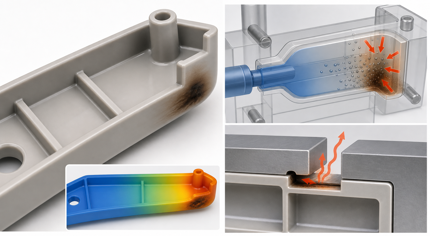
Burn marks in injection molding are dark brown, black or charred-looking areas that usually appear where air or gas is compressed near the end of fill, or where polymer has degraded from excessive heat and residence time. The visible mark is only the symptom. The cause may be inadequate venting, an unfavorable flow path, excessive fill speed, high melt temperature, trapped contamination or material that has remained in the barrel too long.
For buyers and engineers, the location of the mark is often more useful than its color. A mark at the last-to-fill location points toward trapped gas and venting. A mark near a gate or hot-runner transition can point toward shear, dead spots or degradation. A mark that appears after a color change may be contamination rather than a true diesel effect. Diagnose the evidence before asking for a temperature change.
What burn marks look like and why they matter
Burn marks may appear as a small black spot, a brown halo, a dark streak, a roughened patch or a localized area of gloss change. They can occur on a cosmetic face, around a rib end, at a thin-wall endpoint, near a weld line or in a deep pocket. In severe cases, the gas compression can damage the steel surface, create repeated cosmetic defects, or reduce local weld-line strength.
Do not treat every dark mark as burning. Black specks can come from degraded material, carbonized residue, oil, foreign polymer or a dirty hopper. Splay can create a silvery or smoky appearance from moisture or gas. A color change may be a dosing or purge issue. The first inspection should compare location, shape, repeatability, material lot and the production history of the machine and mold.
Burn marks compared with similar defects
| Observed feature | Possible mechanism | Evidence to check |
|---|---|---|
| Dark mark at end of fill | Compressed trapped air or diesel effect | Short shots, vent location and fill-front position |
| Dark streak from gate | Shear heating, degraded residue or hot-runner dead spot | Gate, nozzle and purge sample; residence-time record |
| Random black specks | Contamination, degraded polymer or dirty equipment | Hopper, regrind, screen, purge and material-lot audit |
| Silver or cloudy streak | Moisture, gas or surface splay | Drying record, moisture test and material conditioning |
| Localized roughness with short fill | Gas cannot escape or vent is blocked | Vent condition, mold parting line and air-trap map |
| Mark only after long idle | Residence time or barrel degradation | Idle-time record, purge quantity and restart samples |
그리고 common injection molding defects guide provides a broad troubleshooting map. Review the mold flow and DFM guide when trapped gas follows a gate or end-of-fill feature, and use the injection molding service page for the production route. This page focuses on burn-mark diagnosis, venting evidence and process corrections.
Burn-mark cause, evidence and corrective action

| Cause group | Evidence to collect | Correction direction |
|---|---|---|
| 재료 | Grade, moisture, contamination, regrind and material lot | Dry correctly, segregate lots, control regrind and verify material identity |
| 머신 | Melt temperature, screw speed, back pressure, decompression and idle time | Reduce unnecessary shear or residence time and establish a stable thermal window |
| Mold | Vent depth, vent location, parting-line condition and cavity wear | Clean or extend vents, improve gas escape and restore damaged steel carefully |
| Flow path | Gate location, weld lines, last-to-fill region and short-shot sequence | Change fill profile, gate balance or flow path where the geometry traps gas |
| Hot runner | Zone temperatures, dead spots, nozzle condition and color-change history | Balance zones, purge correctly and repair areas that retain degraded polymer |
Location should guide the next test. If the mark stays at the same last-to-fill location and disappears when the fill speed is reduced or the vent is improved, trapped gas is likely. If it follows a gate or hot-runner branch, inspect shear and residence time. If the mark appears in random locations across cavities, investigate contamination, material degradation and purge history before changing the mold.
Diagnostic sequence for a production complaint
- Document the mark. Photograph the part with a scale, identify cavity and shot number, and note whether the mark is cosmetic or functional.
- Run a controlled short-shot sequence. Compare the location of the mark with the advancing flow front and last-to-fill region.
- Inspect vents and parting lines. Look for blocked vent land, residue, steel damage, flash or a vent that does not reach the trapped-air location.
- Review material history. Confirm grade, drying time, hopper temperature, moisture level, lot, regrind and color change.
- Review machine history. Check melt temperature, screw speed, back pressure, decompression, shot size, cycle time and idle periods.
- Run a purge comparison. Retain purge samples before and after cleaning and compare whether dark residue or unmelted material is present.
- Repeat across cavities. A cavity map can distinguish a tool location from a machine-wide problem.
Use a controlled change matrix rather than changing fill speed, temperature and venting simultaneously. Record part appearance, weight, short-shot location, cycle time and critical dimensions after each change. A correction is more credible when it survives several consecutive shots and does not create short shots, weld-line weakness or dimensional drift elsewhere.
Process corrections that deserve a controlled trial
Fill speed can be reduced near the trapped-air region to lower compression heating, but slowing the whole fill may create a cold weld line or incomplete filling. A multi-stage profile is often more informative than one global speed. Melt temperature should stay within the grade’s processing range; raising it may reduce viscosity but can worsen degradation if the material is held too long. Back pressure and screw speed should be reviewed together because both affect melt preparation and shear.
- Reduce unnecessary residence time and purge after long idle periods.
- Check shot size and cushion so the process is not using excessive melt residence.
- Review decompression and suck-back for air draw-in or unstable recovery.
- Test a lower or staged fill speed near the end-of-fill area.
- Keep mold temperature stable so the frozen layer does not close the vent path too early.
- Retain before-and-after purge samples and record the cleaning method.
Mold, venting and DFM corrections
Vents must be placed where displaced gas actually accumulates, not simply where access is convenient. Thin-wall endpoints, ribs, deep pockets, weld-line intersections and ejector-side air traps may need different venting solutions. Vent depth and land must suit the resin so gas can escape without creating unacceptable flash. A vent that was correct at tool qualification can become less effective after residue, polishing or repeated maintenance.
Gate position and flow path also matter. A gate that forces two fronts to meet around a trapped pocket may produce both burn marks and a weak weld line. DFM review should examine fill direction, end-of-fill locations, shutoffs, ribs and cosmetic surfaces together. Vacuum assistance may be considered for unusually difficult air-trap conditions, but it should be supported by a measured process and maintenance plan.
Validation and acceptance
Define whether the mark is unacceptable by appearance, size, location, function or all four. Cosmetic limits should identify the viewing distance, lighting, approved boundary sample and critical zones. Functional areas may need a stricter rule when a burn mark weakens a seal, interferes with a latch or reduces weld-line strength. Inspect multiple consecutive shots from every cavity after the correction, not only the first clean sample.
For high-risk parts, retain the vent inspection record, purge evidence, material certificate, moisture result, process window and cavity-specific photographs. If the defect returns after a long idle, color change or material-lot change, the production control plan should identify that trigger and the required restart check.
Burn-mark prevention and supplier handoff checklist
- Provide the controlled drawing, cosmetic zones and approved visual standard.
- Identify resin grade, color, filler, drying condition, lot and regrind rule.
- Send defect photos with cavity, shot number, machine and cycle information.
- Mark expected end-of-fill locations, thin walls, ribs and deep pockets in CAD.
- Ask for venting, gate, hot-runner and residence-time risk comments before tool release.
- Require a controlled short-shot or purge comparison when the cause is uncertain.
- Define the inspection sample size and cavity traceability for the correction trial.
- Agree who approves vent cleaning, steel repair, process changes and boundary samples.
For an RFQ or corrective-action request, include part photos, resin and grade, cavity number, process sheet, drawing, annual volume and the production event that preceded the defect. Those inputs allow a supplier to separate venting, material, machine and geometry causes without guessing.
자주 묻는 질문
What is the fastest way to confirm burn marks?
Map the mark against the fill-front and end-of-fill location, inspect the vent, and compare a controlled short-shot sequence with purge and material records. A repeatable location strongly suggests a flow or venting issue.
Can burn marks be fixed by process settings alone?
Sometimes a staged fill profile, lower shear or reduced residence time removes the mark. If the gas trap or vent path is built into the geometry, process changes alone may only move the defect or create a different one.
When do burn marks require a mold modification?
Consider mold work when the mark repeats at a trapped-air location, the vent is blocked or insufficient, the parting line has no practical gas path, or a stable process window cannot meet the approved cosmetic limit.
How should burn marks be measured or accepted?
Use a defined visual standard for cosmetic zones and functional limits for sealing, strength or assembly areas. Record lighting, viewing distance, sample size, cavity and process condition.
What files should a supplier receive before troubleshooting?
Provide photos, CAD, drawing, resin and grade, cavity and shot information, process history, drying and purge records, annual volume, and the function or cosmetic zone affected.